
In a remote area there are problems with DVB-T2 television. The signal is damaged when passing a long distance or when encountering obstacles on the way. During antenna installation, consideration of these factors is necessary to increase the quality of the image on the screen. Install such an antenna for the strength of an ordinary man in the street.
Content
Initial data for manufacturing the antenna K. P. Kharchenko
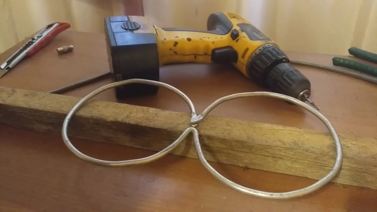
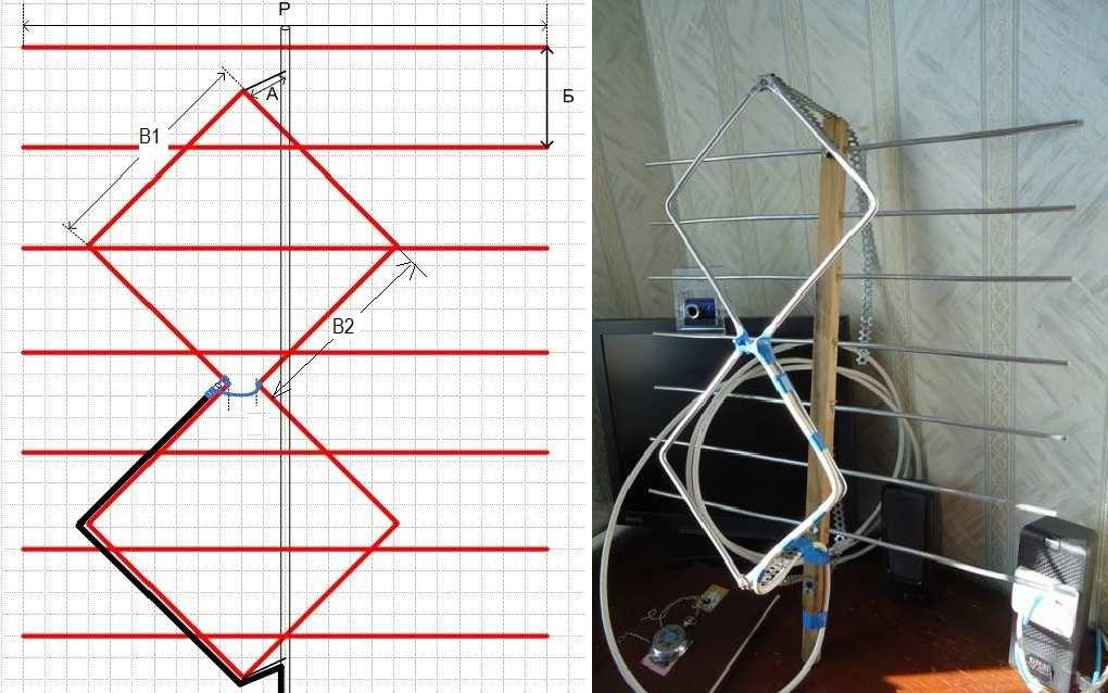
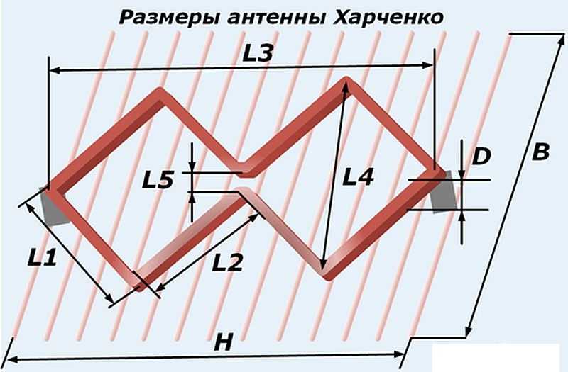
For the correct operation of the future antenna, dimensions are important. The zigzag antenna itself consists of two squares, interconnected in one joint and united in the form of a figure eight. Reflector - an additional part of the device, amplifying the signal. It looks like a grid with transverse rods and a rim around the perimeter. Fastens with an insulator / cable to a curved conductor. Finding a drawing for clarity and a calculator for counting data is easy. It’s worth driving into the search: “Antenna Kharchenko for digital TV do-it-yourself calculation” and the calculator is accompanied by a drawing. So, it’s important to measure:
- The diameter of the conductor of which the biquad part of the structure consists.
- Full product length: from the top of one square to the end of another.
- The diagonal of the square. The squares are identical to each other.
- The distance between the two bends of the conductors at the junction of the ends.
- The lengths of the parties. They ideally coincide, as they are measured in a square.
- The length and width of the reflector.
- The length of the cable / insulator connecting the biquadrat to the reflector.
Calculations must be carried out on a calculator so that there are no errors. They are critical to the result. Some measurements are related to the wavelength of the broadcast signal and must be clearly calculated. However, an error of 2-3 millimeters will not prevent the signal from being transmitted. Carefully need to bend the zigzag contour, it is responsible for the purity of the picture.
Mobile Phone Model
A homemade antenna is also intended for telephones, but is done separately in this case. Materials are sold in hardware or hardware stores:
- copper wire with a diameter of 2-3 mm;
- 50 cm cable for connecting to the device;
- F type connector;
- if you wish, you can install a reflector, then you will additionally need: a reflector made of wire, couplers, a bolt 50 mm long.
The sizes vary, as a basis you can take the following:
- the length of the side of the square is 80 cm;
- the total distance between the corners of the squares is 226 cm;
- in the presence of a reflector, it is necessary to fasten not less than 40 cm from the zigzag frame.
Other sizes are calculated on an online calculator. The assembly of the circuit is as follows. Squares are formed from copper wire, a calculator will tell you where the ends of the conductor will be connected. The gap between the inner corners also follows from the calculations. A type F connector is attached to the middle of the biquad. When installing the reflector, monitor the length of the connector: at least 40 cm. The coupler attaches the connector to the bolt screwed in advance onto the reflector. Pre-solder the cable to the connector to connect the design to the phone.
Model for mobile internet modem
In a remote location from the base station, there are constant problems with the speed of mobile Internet. Harchenko’s antenna design for the modem can speed up the network. The device is invariable and represents the same as the standard model. They rely on the modem frequency during assembly.It is related to the signal length according to the physical formula. Thus, for a frequency of 2.1 kHz, the size of the side of the square is 53 mm.
The antenna is a double construction of squares connected by soldering. A cable is connected to the same place. Again, if desired, the installation of a reflector is possible. It is worth considering the distance between the receiver and the reflector, so that the device works accordingly. You can use an object of the required scale to separate the reflector and the double structure. After taking measurements and assembling the parts, they are fastened with hot-melt adhesive.
Since the modem does not have a connector for connecting the cable, the device is wrapped with wire and only then connected through the cable to the antenna. If the modem model implies a cable connector, the connection is established by the adapter.
Antenna Calculation
The calculation of the necessary parameters for amplifying the DVB T2 signal is done in special programs or online calculators. Both options give a working result. Before that, an interactive map opens with the location of the available TV towers. Find the nearest tower, depending on their location and open the menu. Information on the broadcasting frequency, which plays a central role in measurements, is available in the drop-down list, and it is needed for the following online calculations.

Antenna Assembly for DVB T2
When the necessary details are measured and prepared, you need to assemble the unit. This is done carefully, because the final result affects the transmission of the signal.
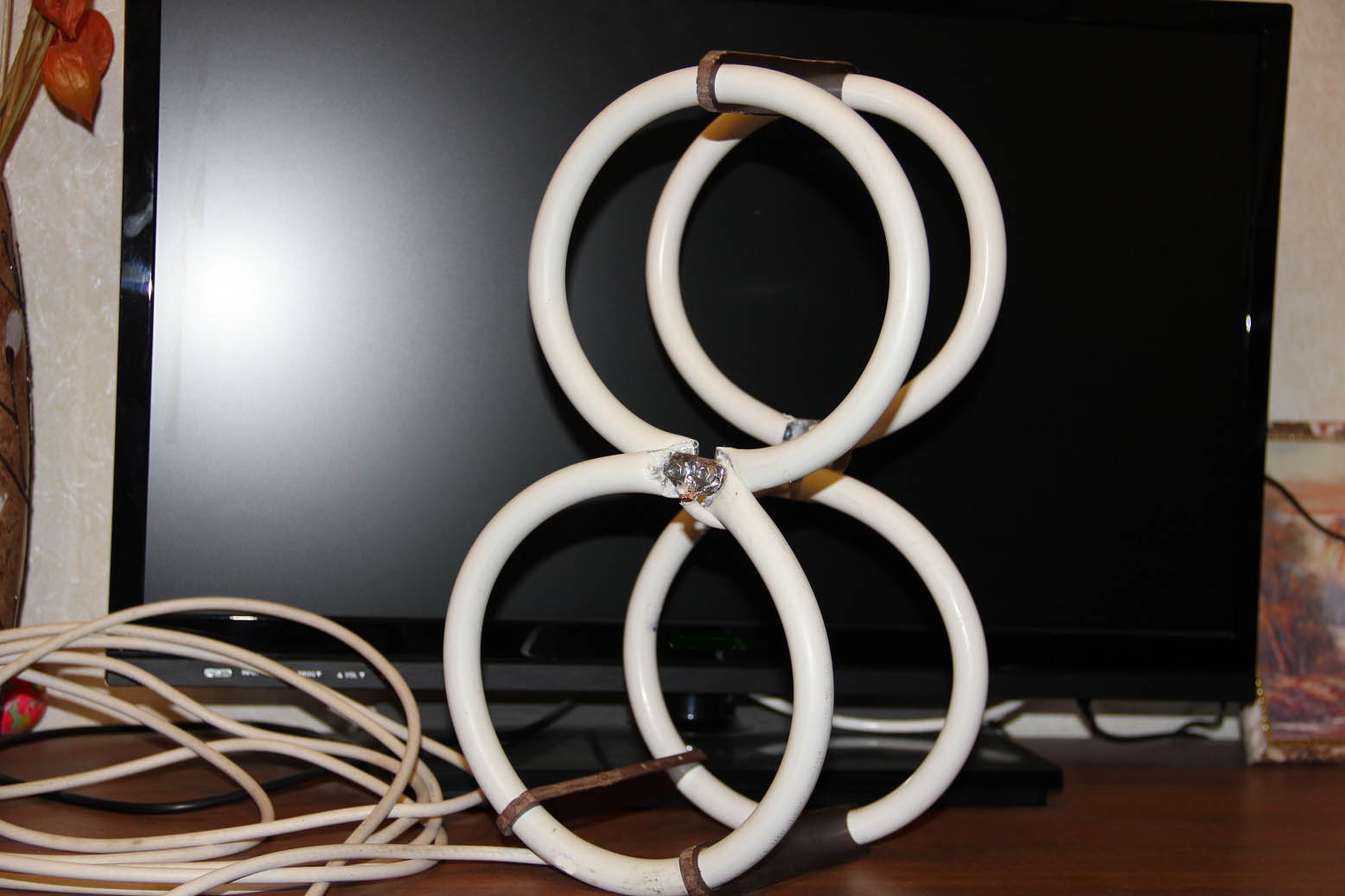
Design description
The biquad part of the antenna fixed at the intersection of two figures is fixed on a wooden rail. A cable is connected to this point, it is pulled to a TV or other device. On the reverse side, a reflector is attached to the rail - transverse metal rods that enhance the incoming signal. The coaxial cable is pressed against the side of the square, depending on the side from which it is connected. Clamped with electrical tape for fixation and conductivity.
Orientation and connection of the antenna
Television is broadcast using a combination of electric and magnetic waves. One transverse, and the second longitudinal. The overlay is transverse-longitudinal, which extends in two directions - horizontal and vertical. This occurs in the form of two sinusoids perpendicular to each other. Each turn carries a positive or negative charge. The location of the objects in the signal transmission circuit is as follows:
- TV tower, it transmits electromagnetic radiation.
- From the edge of a positively charged antenna wing, a current vector is directed to the center. Tension is moving in the opposite direction.
- The next wing carries a negative charge. And the current flows to the end of the antenna. In the same direction, the vector of electromagnetic wave tension extends.
The signal from the antenna is sent to the device in a negative turn.
Homemade Antenna Testing
The final step in installing the device is to calibrate the device to determine the performance. The cable is connected to the receiver, then you need to turn on the receiver and the TV. Then follow the instructions:
- Open the main menu of the receiver and select “automatic channel search”. The search process takes 1-3 minutes.
- They turn on the channel and evaluate the quality of the picture. You can connect channels manually, for this you enter the frequency in the proposed field if there are problems with automatic search.
If the image quality is satisfactory, then the antenna is installed correctly.
The Harchenko model is an affordable way to increase the incoming signal and improve the quality of the image on the screen. The design is easy to manufacture and easy to understand in an hour, with the ability to handle carpentry tools. But the result will appreciate the effectiveness and quality.
Sergei
The stupidity is concrete. This ANTENNA is designed to receive signals from UFOs and VKS! She also catches cockroaches, mice, fleas and mans .... shek.